Pages

Showing posts with label electronics. Show all posts

Monday, May 9, 2016

Adding WiFi and audio streams to the cooler

Introduction

In my previous blog post I finished my audio cooler. It's a small cooler with a tiny audio system that nevertheless sounds good. The only way to control the audio is through a wired connection. It would be a nice addition to have some kind of remote control either by WiFi or Bluetooth. While testing the cooler I've got the idea to connect a Raspberry Pi A+, that was still unused, to the cooler and stream audio over WiFi to the Pi,with the Pi wired with the cooler. This could be useful for a garden party or BBQ where WiFi is available and I don't want to attach the smartphone to the cooler. In this blog post I'll share my experience with installation and operating the software needed for this project on the Pi.

Raspberry Pi A+ (in it's Pimoroni Pibow case)  connected with the headphone jack to the cooler. The Pi has a small Edimax Wifi adapter.

Installing MPD and MPC on the Raspberry Pi

Since I run the Raspberry Pi headless I use SSH login to the Pi. SSH is available for most operating systems with the notable exception of Windows. I already had Raspbian installed on the Pi so first I updated the OS and rebooted.

sudo apt-get update
sudo reboot -h now

Next I created a .conf file for the Edimax WiFi USB adapter. I learned from a previous project that, for a good remote connection, the sleep mode of the Edimax needs to be disabled. In the /etc/modprobe.d folder on the Raspberry Pi a file needs to be created with the name 8192cu.conf (8192cu is the name of the Realtek WiFi chip where the Edimax is based on).

cd /etc/modprobe.d
sudo nano 8192cu.conf

Add the following line in the nano editor and save the file

options 8192cu rtw_power_mgnt=0 rtw_enusbss=0

reboot again

sudo reboot -h now

Now I needed software on the Pi that allows me to remotely play (and organize) music. I installed the MPD (music player daemon) and the very lightweight MPC (music player client) and this server/client combination seemed perfect for this purpose. There are many other clients for MPD, even for Android and iOS, but for now MPC is good enough. To install MPD and MPC on the Pi:

sudo apt-get install mpd mpc

According to some sources on the internet a sound driver (sudo modprobe snd-bcm2835) should be installed on the Pi however I found it was already installed, probably with Raspbian.  This can be checked with the lsmod command.

Adding streams to a playlist

With MPD and MPC installed I'm finally able to stream a radio station from my Pi to the cooler but I needed to add stream urls of my favorite stations. In the example below I add the stream of a Dutch radio station to the current playlist.

mpc add http://icecast.omroep.nl/radio1-bb-mp3

In order to play the stream just type and the added stream starts playing

mpc play

To save the current playlist type

mpc save aplaylist

The file with the name aplaylist.m3u file is created in the folder /var/lib/mpd/playlists with the above url of a stream in it. Of course other urls can be added to the playlist. I've found this list very helpful if you're looking for (Western) European streams.

Adding music to a playlist

To create a playlist of music that is stored somewhere as mp3's just add these files to the folder /var/lib/mpd/music on the Pi. Before the files are copied however the permission of this folder has to be changed. That is done by adding write permission to the group and by changing the group to audio (which is currently root).

sudo chmod g+w /var/lib/mpd/music
sudo chgrp audio /var/lib/mpd/music

Now the mp3's can be copied. To create a playlist of these mp3's first clear the current playlist, create a new one by adding mp3 files and save the playlist.

mpc clear
mpc add /var/lib/mpd/music/my_cool_music.mp3
mpc save cool_playlist
mpc update

The last command updates the database of MPD. By adding more files the playlist increases in length. To play the playlist use the same command as above (mpc play).

Conclusion

A music or internet stream over WiFi to the cooler is a nice addition. MPD is a very stable music player with lots of different clients, perfect for these kind of projects. With MPC I can easily add streams, create playlists, play music or even store mp3's on the Pi. Unfortunately WiFi with a Pi has some downsides too. The Raspberry Pi takes up space in the cooler and it will drain the small battery fast. Therefore as a next step I'll try bluetooth because it probably adds less weight to the cooler and has less power consumption.

Yes, the Raspberry Pi with MPD is a nice addition to the cooler but it has it's drawbacks such as power consumption and added occupied space.


Sunday, May 1, 2016

Audio system for cooler finished

Introduction

A couple of weeks ago I started to make a tiny audio system for our cooler. In my previous blogpost I described all the audio components that I chose for this project. I wanted the components to be small since I didn't want to waste too much space in the cooler. With the audio components in hand I could design other parts for the audio system. I needed an enclosure for most of the audio components and a simple console to operate the audio. The parts were 3d printed with my Hephestos 2.

The complete audio system in the lid of the cooler. Most components are placed in the 3d printed enclosure.

The enclosure for the amplifier

While designing I borrowed heavily from Adafruits Trinket Neopixel led longboard, a project that upgrades a longboard with Neopixel LEDs. The battery, amplifier and Powerboost 500c had to fit into a small enclosure for protection. The enclosure needed several rectangular cavities for a switch, micro usb and wires.

Enclosure (bottom and lid) for the battery, amplifier and Powerboost 500c designed in FreeCAD.
The Powerboost 500c and the amplifier are screwed directly to the lid of the 3d printed enclosure while the Li polymer battery is pressed to the bottom by a PLA strip.

Kemo 3.5W Amplifier and Adafruit Powerboost 500c are screwed directly to the lid of the 3d printed enclosure. The battery is placed firmly under a PLA strip.
In the front the enclosure with the Powerboost and amplifier screwed to the lid. On top of the enclosure is the lock.

Attaching the enclosure to the cooler lid

I needed a simple design to attach the enclosure firmly to the inside of the cooler lid but I also wanted to be able to slide the enclosure out and back in again if necessary. Again I took an idea from the Adafruit Trinket Neopixel LED longboard . I designed a slide lock that consists of two pieces a mount and a lock. The lock slides into the mount until the stop on the lock reaches the mount.

The lock fits into the mount but can be slided in and out. Two two holes in the lock are used to screw the lock to the enclosure.

The console

I also needed some kind of console to operate the audio system. I decided to keep it simple with a 3.5mm audio plug and volume control. The on/off switch is in the enclosure (for now).

Back side of the console with the 3.5mm audio plug for audio-in and 10K potentiometer for volume control.

Preparing the cooler

Preparing the cooler is pretty straightforward. First I drilled a circular hole in the top of the lid just wide enough (68mm) for the speaker. This hole is centered on the top. Next I cut with my Dremel a rectangular hole in the side of the lid just wide enough for the console to fit. With these two holes the cooler lid was ready and all components could be attached. The speaker was screwed onto the lid while the console and the mount were glued to the lid. Glueing proved to be difficult. I tried  two-component expoxy and superglue (cyanoacrylate base) for glueing the enclosure to the cooler lid but the enclosure came loose in both events. Next I tried double-sided tape and this works however time will tell if it is a lasting solution. With most of the work done it is time to test my audio enabled cooler. Which some nice weather coming up I'll test the cooler outside and report back the results.

Circular hole in the center of the lid for the speaker to fit in.
The finished products. In the upcoming month I'll see how it performs.

Sunday, April 10, 2016

Making a tiny audio system for our cooler (part 1)

Introduction

For picknicks we use a small cooler and with the upcoming spring and summer it seems like a great idea to add an audio system to it. Most DIY coolers with audio that I found on the internet are huge. Not only do they have large speakers and amplifiers but they also have a huge lead battery hardly leaving any space for the picknick gear. I want a tiny, one speaker system that sounds nice but is lightweight and leaves plenty of room for the other stuff. I also wanted it nicely integrated in the cooler without too many wires. I therefore started to design and build one.

Choosing the audio components

I started this project by choosing a suitable battery. As stated above lead batteries are relatively large due to their low energy density. Lithium polymer batteries on the other hand have large energy density, four to five times higher than lead according to this source. Prices of polymer batteries are also very reasonable nowadays.

Lead-acid battery (left) and polymer battery (right) side by side on the small cooler. The much bigger and heavier lead-acid battery has a capacity of 5000mAh (6V) while the lithium polymer battery has 1200mAh (3,7V). The lithium polymer with it's four to five times larger energy density is therefore perfect for my small audio system.

Monday, February 29, 2016

Case for a FM-radio (Velleman MK194)

I have a MK194 radio kit from Velleman and turned it into a radio some  time ago. The radio looks pretty cool with all the electronic components visible but the wooden case was awful. I therefore decided to build a new case for it. Of course I want to use my Hephestos 2 printer from BQ to make this case.

First I designed a case in FreeCAD. I use FreeCAD for a couple of weeks now, together with OpenScad, but this is the first design with multiple parts that I create with it. After several iterations I finally decided to have a design consisting of three parts. A box, a support plate for the radio PCB and a lid. The radio fits into the support and the lid which are then screwed onto the box.


Design for the radio case made with FreeCAD consisting of three parts (the red part just represents the MK194 PCB). I made a nice radius on the lid and the MK194 fits nicely between the support and the lid.
I think the radio looks really nice now much better than the wooden case at least. I'm getting the hang of FreeCAD. The learning curve is steeper than OpenScad's but it is worth it. Creating a more complex design is just faster with FreeCAD than with OpenScad (at least for me).
Here are the .stl files:
My FM-radio on my electronics workbench.

Friday, February 12, 2016

What to make for Valentine's day?

What to make for Valentine's day? A bare perfboard with a Valentine's chaser (basically a 555-chip, 4017 decade counter and a handful of leds) doesn't look too impressive. That's why I made this heart shaped wooden box with a laser cutter. Both printboard and battery fit nicely into the box. Three bolts, nuts and washers to finish the job.

The file for the laser cutter (.svg) can be found here.

And here is a 3d printer file (.stl) of a little dock for the heart.


Sunday, January 31, 2016

Darth Vader chest box finished

Introduction


The last couple of weeks I wrote about the second iteration of the Darth Vader chest box that I was making. Now that it is completely finished I'll here a summery of the project with the main properties of the box, a YouTube video of the chest box in action, schematics and links to all the blog posts about this project.

Darth Vader chest box properties


  • enclosure laser cut plywood (6mm)
  • easy control with four push buttons
  • DIY voice changer circuit with Holtek HT8950A
  • LM386 amplifier
  • build-in speaker
  • audio-in (3.5mm)


Finishing the job


When I started the Darth Vader chest box early december 2015 I didn't expect it would take me almost two months. Finally this week I finished it and I'm happy to say that it works great. For a couple of weeks it was almost finished but there always seemed to be some work to be done. A major problem was that I couldn't get the 3D printed container for the audio-jack right. I tried it several times at my local fablab but it just didn't fit. Finally I ordered the container from 3D Hubs and it had a perfect fit.

Audio-jack container (right) and volume knob (left). The blue parts were printed by me while the black parts were ordered through 3D Hubs. the X,Y-dimensions of the blue parts were off probably due to overextruding. The black parts were fine.

Next I made all the external connections to the perfboard, always a delicate job. I mounted the perfboard and all other components to the laser cut plywood parts.

All electrical components(buttons, perfboard, battery compartment, audio-jack, on/off switch)  fitted to the plywood parts. The speaker is fitted to the front panel of the chest box.
Finallly I glued all laser cut parts together with regular wood glue except for the front panel. When the batteries need replacement or some other kind of problem occurs I still have access to the inside of the chest box.

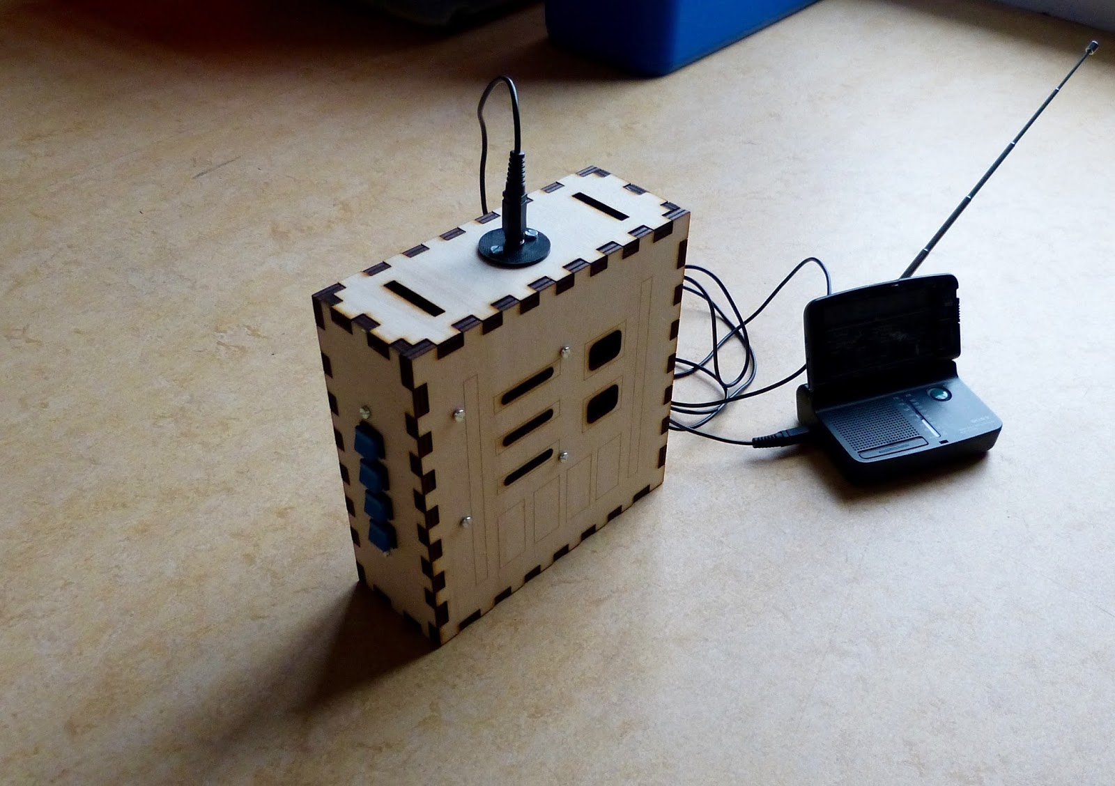
Chest box with FM radio connected to audio-in.

Finished chest box with laser cut parts glued to the front of the box.
Schematics of the Darth Vader chest box.

As a last step I wrote an instructable of the chest box providing anyone interested with the schematics, files for the laser cutter and 3D parts. In the mean time here are the links to the other blog posts on this chest box:
http://eribuijs.blogspot.nl/2015/12/darth-vader-voice-changer-20-ht8950a.html
http://eribuijs.blogspot.nl/2015/12/darth-vader-voice-changer-20-creating.html
http://eribuijs.blogspot.nl/2015/12/homemade-darth-vader-voice-changer-20.html
http://eribuijs.blogspot.nl/2016/01/designing-parts-for-darth-vader-chest.html
http://eribuijs.blogspot.nl/2016/01/the-darth-vader-chest-box-is-almost.html

Monday, January 11, 2016

The Darth Vader chest box is almost finished

Introduction

The last month I've been working on my Darth Vader chest box. I've designed and built my own circuit with the Holtek HT8950A voice modulator, I create a laser cut case and designed 3D printed parts for the chest box. Since I had to learn a lot of new techniques, e.g laser cutting and 3D printing, this is by no means an easy project for me. With the project in it's final stages now some design problems turn up that need fixing.

Soldering the board.

This week I soldered the components to the board. First I soldered the voice changer components and made sure this part of the circuit is working. Next I soldered the amplifier. I tested the total circuit and it worked the first time which is always a joyful moment. I find the Adafruit perma-protoboard very easy to work with since I'm able to copy the layout from the breadboard. Next I grouped all the buttons that operate the HT8950A on a board and soldered them to a piece perfboard. The buttons on the perfboard fit nicely into the laser cut side panel that I already made. Operating the chest box is easy with this (a major issue with my previous chest box).

Soldered perma-protoboard and breadboard side-by-side.
Close-up of the soldered board with the HT8950A voice changer chip on the right and the LM386 amplifier on the left.
Operating the voice changer with this panel should be easy.

Design issues

Last week I made 3D printed parts for the front of the chest box. Unfortunately I found that these parts didn't look good with the laser cut box. The plastic parts just didn't do justice to the laser cut plywood. I therefore decided to laser cut all the parts that sit on the from of the box with I think is aesthetically more pleasing.

Another problem arose with the female audio jack connector that I need to plug in the microphone. The thread of this 3.5mm connector just isn't long enough to be fitted onto the 6mm thick plywood. I designed a container to solve this. The audio connector fits into this container and the container is screwed to the case. Hopefully this container solves the problem.

Container for the audio jack connector created with Openscad. The container, screwed to the chest box, will keep the audio connector tightly to it's place.

Yet unsolved problems

  • I need to attach a nylon belt to the chest box. I'm thinking about popper snap fasteners attached to the belt to open or close the belt.
  • The HT8950A works fine with a proper audio signal as input but the microphone that I have, a small electret microphone, doesn't give any audible output (except for noise). I assume that the signal is to weak and therefore needs amplification.


Thursday, December 24, 2015

Homemade Darth Vader Voice Changer 2.0 (work in progress)

Introduction

The last couple of weeks I worked on a homemade voice modulator that is easy and cheap to built. First I'd like to mimic the Darth Vader Voice Changer, but with the press of a button it can be changed to robot or helium kind of voice effects. Last week I've steadily continued my work. The project has two main parts, the electronics and the case.

Electronic circuit

For the project I choose the HT8950A voice modulator from Holtek as the heart of the circuit. It is cheap, versatile and easy to work with. I previously had the voice modulator working. I only had to amplify the signal which seemed simple enough. Well, that turned out to be a bit more troublesome than expected. After connecting the LM386 to the circuit and powering it up an annoying hiss was introduced. After some experimenting I figured that the breadboard was to blame and decided to copy the circuit to another breadboard. Although on the new breadboard the hiss appeared somewhat reduced but it was still at an unacceptable level. Even when I removed the input signal from the LM386 the hiss continued. I connected the HT8950A with a audio-jack to an external amp. I wanted to make sure that the hiss was coming from the LM386. With the external amp the hiss was gone. The fact that I had hiss without an input signal indicated that the supplied voltage wasn't clean.  To clean it up I placed a small capacitor (10nF) from pin 6 (V+) to ground and voila the hiss was gone (see schematics below). It took me some time but I'm almost ready to finish this circuit and solder it to perfboard.

Two (almost identical circuits) with the Holtek HT8950A voice modulator and the LM386 amplifier. Both circuits gave a hiss which was unacceptable. Eventually a simple 10uF capacitor from pin 6 to ground did the trick for me. 
Schematics of the Darth Vader voice changer. I was able to eliminate all the hiss and noise from the LM386.

Printing the case.

I decided previously to make a T-slot plywood case for the Voice Changer but I'm not satisfied with the result. First I made a beginners mistake with the tab width. It was chosen poorly resulting in fragile edges of the case. Also I discovered that a T-slot case is not the best choice for this project. The case needs to be sturdy and the T-slot isn't. I'm afraid it will fall apart when in use. Therefore I'll made a regular finger joint that will be glued together. This new case was much better. Gone are the fragile edges and I'm confident that glued together it will be very sturdy.

Laser cut case made out of plywood. I first used a T-slot type of case but made a beginners mistake with the tab width and positioning. As a consequence the edges become very fragile. The front of the case has engravings for the positioning of large controls of the voice changer. These controls on the front will we dummies just to mimic the look of a Darth Vader voice changer. The actual controls will be on the side of the box.
Laser cut case with regular finger joint. This attempt is much better.

Monday, December 7, 2015

Darth Vader voice changer 2.0 (HT8950A)

Introduction

Last June I wrote about a Darth Vader voice changer that I made. Back then I used the Velleman MK171 kit as the electronic part of the voice changer. Although it worked pretty well I felt that some area's needed improvement. First, I couldn't get the pushbuttons mounted on the housing to work making it hard to switch the voice effect. Second, I didn't like the limitations that obviously come with such a kit; you're more or less bound to the design as intended by Velleman.

The HT8950A chip

For this project I wanted to deviate from Velleman's MK171 design and experiment with the HT8950A chip, the heart of the kit. The HT8950A chip from Holtek is a voice modulator that provides two special effects, Vibrato and Robot (pin 2 and 5 respectively). It also provides frequency level shifting enabling the user to shift the frequency up or down (pin 3 and 4 respectively). This is perceived as a higher or lower pitched sound resulting in a 'Darth Vader' type of sound when the frequency is shifted two steps lower. More detail on this can be found in the datasheet of the HT8950A. An external LED connected to the LAMP pin (pin 11) changes it's brightness when the input voice signal changes. Pin 12, the AUDIO, provides the resulting sound that can be amplified.

Breadboard with in the middle the HT8950A. For this chip relatively few components are needed to get te voice modulation to work.
The chip can be acquired by buying the MK171 kit from Velleman. This kit also provides you with a LM386 amplifier however it is cheaper to buy the HT8950A without the other (generic) components from eBay or Aliexpress. If you do so make sure that your supplier of your choice has sufficient positive feedback.

Building it on the breadboard

On the datasheet of the HT8950A (page 5 onward) schematics can be found how to connect the chip. The amplifier of  the schematic on page 5 or 7 can easily be exchanged for another one of your liking. I'll probably use the LM386 because it's cheap and I have several on stock. In order to operate the HT8950A one only needs a couple of generic components (7 resistors, 5 capacitors, an LED and a zener diode) so building it is not too complicated.

First I built the circuit on the breadboard without an amplifier. The HT8950A actually has it's own built-in amplifier consequently connecting a small speaker to AUDIO (pin 12) is sufficient to give an audible sound, though barely. Alternatively a headphone can be used. This is especially useful if your roommates start complaining about the weird noise. Later I also connected a homemade amplifier to the circuit (to my roommates despair). The Robot mode sounds good but while testing the frequency level shifting mode a lot of noise became apparent. Placing a capacitor over pin 8 and 9 (AO and AIN respectively) reduces this noise considerably. Optionally a 25K potentiometer can be placed between the 33K resistor and pin 8 to tune the sensitivity of the microphone or any other sound input.

Although I'm rather pleased with the result. I would like to take this experiment a little further. Next I'll try to further optimize the sound, add the LM386 amplifier and solder the circuit to a perf board. Then I'll either use the plywood housing that I made for the original version or make a lighter one.

Overview of the circuit. The Audio in is coming from an old FM radio (top-left). I'm using a headphone to listen to the modulated sound while keeping my roommates happy.

Schematics of the experiment. The capacitor between AO and AIN varied between 47nF an 220nF to reduce the noise. I found that the 47nF gave the best results.

Thursday, October 29, 2015

Building a robot cart (Experiment 32 of Make:Electronics) finished

In my previous post about the robot cart I described how I finished the cart and tested the circuit on the breadboard. I only had to solder the circuit to the perf board and mount the board on the cart. Simple, right. Unfortunately it wasn't that simple. After soldering I tested the board and discovered that there was a problem. The motor would spin and when I pushed the button it would reverse as intended however it never reverted to the original direction. I replaced several components such as the 555 chip but that didn't help. When measuring the voltage on the pins of the 555 chip I found that it worked exactly as intended. I was mystified and beginning to feel desperate but then I recalled that there was an errata page on the book Make:Electronics.  On this page I found someone describing the same problem that I had. Charles Platt the author of the book acknowledges the problem and possible solutions are offered. Searching on the internet for 555 timer relay I found a comparable schematic on cdelectronics.com. It basically adds two diodes to the schematic of the book (figure 5-98). One diode from the output of the 555 timer to the relay (to energise the coil) and a second across the coil.

The result of this experiment. A finished, although somewhat improvised, robot cart. The electronics work great but the cart is susceptible to failure due to the alligator clips. It also runs way to fast damaging the switches while running into a wall.
I added the two diodes to my board and tested it. I found that it works on 6V DC but barely. Due to the voltage drop on the first diode just 3.8V remains over the coil, just enough to energise it (for this specific relay: SRC-S-06VDC). If the battery voltage drops below 6V the coil is no longer energised. I therefore decided to use 9V DC block battery instead of 6V. This should provide a wide margin for operation without damaging the relay.

NOTE: I found that other people such as +Virgil Machine were having good results with just a diode across the coil. Here is a link to his blog page. That didn't work for me possibly to due the relay that I use.

Next I'll mounted the perf board (I used the handy half-size perma protoboard from Adafruit for this which I picked up for 4.95 euro) and the battery on the cart. I connected the the motor, battery and switches to the perf board. Then it was time to test the cart. The first test went miserably because the cart didn't react to the switches. I then connected my bench power supply to the cart and it worked fine. I figured that the capacity of one block battery is insufficient to power the cart. I solved this by placing two block batteries in parallel which doubles the capacity of the power source.

Testing the nearly finished cart with two block batteries in parallel. The block batteries are connected with alligator clips. The higher capacity was needed to power the circuit and the motor (which is very power hungry).

With the power problem solved I made the last additions to the cart. I added an on/off switch and a glued a piece of plywood with velcro on it to the back of the cart. I attached the two block batteries to the velcro. Lastly I glued rubber to the front wheel to get more grip.

While testing the cart I noted that it runs way to fast. I already damaged a sensor when cart hit a closet. Also the alligator clips come loose when the cart hits something. Nevertheless I feel I have nearly completed this experiment. I'll probably replace the motor for one with lower RPM (and a less power hungry one).


The perf board attached to the top of the cart with two bolts and nuts. Note the two diode are added to the circuit.
It doesn't look pretty with all those wires but it works. The batteries are attached to the cart with velcro.
Side view of the robot cart. A piece of plywood is added to the back of the cart to accommodate the batteries. I glued rubber to the front wheel of the cart to increase traction.
The other side of the finished robot cart.

Friday, October 23, 2015

Homemade igniter

My sons are a week off from school and since it was rainy we decided to make an igniter for fireworks or model rockets. The type of igniter that we made comes from Grant Thompson "The King of Random". He entertains an excellent YouTube channel with lots of great experiments with simple materials. The igniter is easy using only some stranded copper wire, matches and tape. The stranded wire is stripped and a single copper strand is connected to the another wire. A match is then placed between the two wires and the single copper strand is then fixed against this head. A notch made in the head of the match keeps the strand in its place. Tape is used to fixate all the parts. The cool part of this project is that you can remotely ignite the match.

We used both two 9V alkaline block batteries in parallel (as suggested by Grant Thompson) and a 6V battery that I salvaged from an old pump. Both solutions work perfectly although with the 9V block batteries the match ignited faster. I used two alligator clips to connect the igniter to the battery. I placed the igniter is a third hand to prevent that it sets something on fire by accident.

A word of caution. The 6V battery that we used is of the sealed lead acid type. Since you will short circuit the battery it is safer to use a alkaline battery instead of rechargeable battery (lead acid, Li-ion, NimH etc). Rechargeable batteries can explode or catch fire when short circuiting it. Since I short circuited my lead acid battery no longer than a few seconds I figured that there was no danger. In conclusion it is safer to use the alkaline batteries and short circuit them only for a few seconds in a row.

So how is it possible that the match catches fire. I already mentioned that you short circuit the battery. According to Ohm's law I = V / R. The resistance R is very low (it's just the copper strand) while the voltage V remains the same. The current is therefore very high. The heat produced in the circuit is proportional to I2 * R * t. With the current squared the heat rapidly increased with increasing current (even though the resistance is low). At a certain point the heat ignites the head of the match.

We used these simple tools and materials to make the igniters.
The fruits of hard labour.
Make sure the strand of copper fits into the notch of the matches head.

Friday, October 16, 2015

Building a robot cart (Experiment 32 of Make:Electronics)

This experiment is about building a little robot cart. Make:Electronics describes all the steps that needs to be taken in great detail beginning with the cart and then the circuit. This experiment is a lot of work but I think it is worth it because you make a complete robot from the bottom up. The cart is much smaller than I initially thought and making small things brings their own set of problems in terms of precision and tools needed.

The cart needs a motor and I salvaged one from an old RC car that was lying around in the house. For this project I use a 6V DPDT relay. I decided to make the circuit first. I had some problems with the relay because the switch is connected differently than the one used in the book. Luckily this was easily solved by looking at the datasheet of the relay. I tested the motor on the circuit and it worked well.

The cart made out of plywood with a motor that I salvaged from a old RC car. I grinded away some unnecessary parts of the housing of the motor. 

Next I created the cart. I made the cart of 1/4" thick plywood and not the ABS material that is suggested in Make:Electronics since I have no experience with ABS. I cut the plywood and connected the pieces with screws and bolts and nuts for the wheels. The cart looks pretty good (I think) and maybe a good platform for further experiments. There are two potential problems with the cart. First the wooden wheels lack grip. Maybe I'll cover the surface of the wheel with rubber tape to overcome this. Second the motor is spinning fast maybe too fast for the cart. The cart might crash because of this. This could be solved by adding some gears to the motor but that would complicate things. For now I will just wait and see what happens once the cart is finished.

Next I will solder the circuit on a piece of perfboard and fit it on the cart. The book describes the principle of limit switches to create a better steering mechanism (p278). The author doesn't describe in detail how to add this to the robot cart but I might be a nice addition to this experiment.

Circuit of the robot cart with a 555 timer triggering the relay. The motor is reversed when the relay is energised. The LED indicates that the 555 timer is triggered (by the switch). With the trimmer sets the length of the 555 pulse The pin lay-out of the relay is different from the ones described in Make:Electronics (p58).
Overview of the cart. The hinged trailing wheel is not yet connected to the cart.

Wednesday, October 7, 2015

Homemade camera dolly

Finished camera dolly made out of Makeblock and plywood. The plywood is painted black with a regular (alkyd) spray paint.
I make a lot of video's of our projects so I figured a camera dolly would be a nice addition. I could buy one of course but making one is a lot more fun. About a year ago I bought a Makeblock starter robot kit. The supplier that I bought it from was offering it with a nice discount at the time. The purpose of Makeblock is prototyping but I never used it, until now. Makeblock offers a versatile, sturdy and extensible platform for the camera that seemed very suitable for this project. Even better an Arduino Leonardo clone is included so programming it is not too difficult.

Makeblock claims they have an open source hardware and software platform. Makeblock uses an Arduino clone, called Baseshield, and Arduino is truly open source software platform. The Baseshield uses the RJ25 a 6 pin connector (known for their use in telephone lines) to interface with their sensors. Although this RJ25 is easy to use it is not so easy to connect a generic electronic component to it. This can be avoided by just replacing the  Baseshield with a regular Arduino (EDIT: something I haven't done in this project). Furthermore Makeblock provides free downloadable CAD drawings of their mechanical parts such as the beams and gears.

I found an example of a Makeblock camera dolly in the internet but unfortunately no documentation was provided. I therfore had to improvise using the Makeblock components that I had. My Makeblock dolly also has four wheels and only a couple of beams are needed. It is very sturdy. It uses two 6V motors that came with the starter set. Each engine has a simple transmission to a wheel via a belt and a couple of gears. The combination of the gears reduces the speed of the motor.

I needed a solution to attach the camera to the Makeblock beams. I decided to make a plywood frame for the camera since I have a lot of plywood lying around. Plywood is cheap but strong enough for this application. With this plywood frame the camera is able to tilt up and down and rotate. With the bolt and nuts I can fix the camera in a desired position.

The plywood frame that serves as a mount for my Xacti camera. The frame is made out of 1/2" thick plywood cut in strips of 1-1/4" width. The frame is assembled with 1/4" bolds and nuts.

The camera mounted on the frame. 

I had to place the camera a bit outside the frame to be able to open the display.

I could have used any other material to make a camera dolly than Makeblock but that would probably have taken considerably more time. On the other hand using wood or plastic is much cheaper. The aluminium mechanical parts are fairly expensive. Some Makeblock parts can easily be replaced by cheaper alternatives. For instance all screw are 4 mm screws which can be bought at the local hardware store. Same goes for shafts and nuts.

The dolly in action with the still unpainted frame.

All in all I'm happy with the result although the dolly still needs some work. First the dolly has a slight tendency to move to the left. I exchanged motors, gears and wheels from left to right but that didn't made a difference. Also the dolly has no suspension at all which can lead to unstable video's.

I added a YouTube video below to demonstrate the camera dolly.

Thursday, September 17, 2015

Breadboard malfunction (redo experiment 29 and 30 of Make:Electronics)

During experiment 29 and 30 of Make:Electronics I noticed that the circuit were very susceptible to noise to the point that it really interfered with the experiments. While thinking about it I suspected that something was wrong with the breadboard. I decided to redo both experiments with a another breadboard (but without the low pass and high pass filter). I immediately discovered that the sound was more clear than before. I also discovered that at 9V the circuit only took 40mV whereas the same circuit on the old breadboard took 200mV. A clear sign that the old breadboard was malfunctioning (possibly due to a burn-out).

Previously I wrote about the TEA2025B amplifier becoming very hot. So hot that I decided to reduce the voltage of the circuit from 9V to 4.5V. The same amplifier in the current breadboard is not hot at all even at 9V! Not surprisingly since the heat generated by the amplifier is proportional to the square amperage.

The lesson here that when that even the unsuspected elements can be a variable in experiments.


Redoing experiment 29 and 30 on another breadboard was worth. At 8,9V the circuit only needs 40mA. Not only did I get rid of all the noise also the circuit needed only one fifth of the amperage. Visible on this image is part 2 of experiment 29.
Closer look at the breadboard with on the left the 555 chip with a black and blue trimmer surrounding it. On the right the TEA2025B amplifier. The circuit on the breadboard is same as the shown in figure 5-41 of the book without the low and high pass filter.