Pages

Showing posts with label amplifier. Show all posts

Monday, May 9, 2016

Adding WiFi and audio streams to the cooler

Introduction

In my previous blog post I finished my audio cooler. It's a small cooler with a tiny audio system that nevertheless sounds good. The only way to control the audio is through a wired connection. It would be a nice addition to have some kind of remote control either by WiFi or Bluetooth. While testing the cooler I've got the idea to connect a Raspberry Pi A+, that was still unused, to the cooler and stream audio over WiFi to the Pi,with the Pi wired with the cooler. This could be useful for a garden party or BBQ where WiFi is available and I don't want to attach the smartphone to the cooler. In this blog post I'll share my experience with installation and operating the software needed for this project on the Pi.

Raspberry Pi A+ (in it's Pimoroni Pibow case)  connected with the headphone jack to the cooler. The Pi has a small Edimax Wifi adapter.

Installing MPD and MPC on the Raspberry Pi

Since I run the Raspberry Pi headless I use SSH login to the Pi. SSH is available for most operating systems with the notable exception of Windows. I already had Raspbian installed on the Pi so first I updated the OS and rebooted.

sudo apt-get update
sudo reboot -h now

Next I created a .conf file for the Edimax WiFi USB adapter. I learned from a previous project that, for a good remote connection, the sleep mode of the Edimax needs to be disabled. In the /etc/modprobe.d folder on the Raspberry Pi a file needs to be created with the name 8192cu.conf (8192cu is the name of the Realtek WiFi chip where the Edimax is based on).

cd /etc/modprobe.d
sudo nano 8192cu.conf

Add the following line in the nano editor and save the file

options 8192cu rtw_power_mgnt=0 rtw_enusbss=0

reboot again

sudo reboot -h now

Now I needed software on the Pi that allows me to remotely play (and organize) music. I installed the MPD (music player daemon) and the very lightweight MPC (music player client) and this server/client combination seemed perfect for this purpose. There are many other clients for MPD, even for Android and iOS, but for now MPC is good enough. To install MPD and MPC on the Pi:

sudo apt-get install mpd mpc

According to some sources on the internet a sound driver (sudo modprobe snd-bcm2835) should be installed on the Pi however I found it was already installed, probably with Raspbian.  This can be checked with the lsmod command.

Adding streams to a playlist

With MPD and MPC installed I'm finally able to stream a radio station from my Pi to the cooler but I needed to add stream urls of my favorite stations. In the example below I add the stream of a Dutch radio station to the current playlist.

mpc add http://icecast.omroep.nl/radio1-bb-mp3

In order to play the stream just type and the added stream starts playing

mpc play

To save the current playlist type

mpc save aplaylist

The file with the name aplaylist.m3u file is created in the folder /var/lib/mpd/playlists with the above url of a stream in it. Of course other urls can be added to the playlist. I've found this list very helpful if you're looking for (Western) European streams.

Adding music to a playlist

To create a playlist of music that is stored somewhere as mp3's just add these files to the folder /var/lib/mpd/music on the Pi. Before the files are copied however the permission of this folder has to be changed. That is done by adding write permission to the group and by changing the group to audio (which is currently root).

sudo chmod g+w /var/lib/mpd/music
sudo chgrp audio /var/lib/mpd/music

Now the mp3's can be copied. To create a playlist of these mp3's first clear the current playlist, create a new one by adding mp3 files and save the playlist.

mpc clear
mpc add /var/lib/mpd/music/my_cool_music.mp3
mpc save cool_playlist
mpc update

The last command updates the database of MPD. By adding more files the playlist increases in length. To play the playlist use the same command as above (mpc play).

Conclusion

A music or internet stream over WiFi to the cooler is a nice addition. MPD is a very stable music player with lots of different clients, perfect for these kind of projects. With MPC I can easily add streams, create playlists, play music or even store mp3's on the Pi. Unfortunately WiFi with a Pi has some downsides too. The Raspberry Pi takes up space in the cooler and it will drain the small battery fast. Therefore as a next step I'll try bluetooth because it probably adds less weight to the cooler and has less power consumption.

Yes, the Raspberry Pi with MPD is a nice addition to the cooler but it has it's drawbacks such as power consumption and added occupied space.


Sunday, May 1, 2016

Audio system for cooler finished

Introduction

A couple of weeks ago I started to make a tiny audio system for our cooler. In my previous blogpost I described all the audio components that I chose for this project. I wanted the components to be small since I didn't want to waste too much space in the cooler. With the audio components in hand I could design other parts for the audio system. I needed an enclosure for most of the audio components and a simple console to operate the audio. The parts were 3d printed with my Hephestos 2.

The complete audio system in the lid of the cooler. Most components are placed in the 3d printed enclosure.

The enclosure for the amplifier

While designing I borrowed heavily from Adafruits Trinket Neopixel led longboard, a project that upgrades a longboard with Neopixel LEDs. The battery, amplifier and Powerboost 500c had to fit into a small enclosure for protection. The enclosure needed several rectangular cavities for a switch, micro usb and wires.

Enclosure (bottom and lid) for the battery, amplifier and Powerboost 500c designed in FreeCAD.
The Powerboost 500c and the amplifier are screwed directly to the lid of the 3d printed enclosure while the Li polymer battery is pressed to the bottom by a PLA strip.

Kemo 3.5W Amplifier and Adafruit Powerboost 500c are screwed directly to the lid of the 3d printed enclosure. The battery is placed firmly under a PLA strip.
In the front the enclosure with the Powerboost and amplifier screwed to the lid. On top of the enclosure is the lock.

Attaching the enclosure to the cooler lid

I needed a simple design to attach the enclosure firmly to the inside of the cooler lid but I also wanted to be able to slide the enclosure out and back in again if necessary. Again I took an idea from the Adafruit Trinket Neopixel LED longboard . I designed a slide lock that consists of two pieces a mount and a lock. The lock slides into the mount until the stop on the lock reaches the mount.

The lock fits into the mount but can be slided in and out. Two two holes in the lock are used to screw the lock to the enclosure.

The console

I also needed some kind of console to operate the audio system. I decided to keep it simple with a 3.5mm audio plug and volume control. The on/off switch is in the enclosure (for now).

Back side of the console with the 3.5mm audio plug for audio-in and 10K potentiometer for volume control.

Preparing the cooler

Preparing the cooler is pretty straightforward. First I drilled a circular hole in the top of the lid just wide enough (68mm) for the speaker. This hole is centered on the top. Next I cut with my Dremel a rectangular hole in the side of the lid just wide enough for the console to fit. With these two holes the cooler lid was ready and all components could be attached. The speaker was screwed onto the lid while the console and the mount were glued to the lid. Glueing proved to be difficult. I tried  two-component expoxy and superglue (cyanoacrylate base) for glueing the enclosure to the cooler lid but the enclosure came loose in both events. Next I tried double-sided tape and this works however time will tell if it is a lasting solution. With most of the work done it is time to test my audio enabled cooler. Which some nice weather coming up I'll test the cooler outside and report back the results.

Circular hole in the center of the lid for the speaker to fit in.
The finished products. In the upcoming month I'll see how it performs.

Sunday, April 10, 2016

Making a tiny audio system for our cooler (part 1)

Introduction

For picknicks we use a small cooler and with the upcoming spring and summer it seems like a great idea to add an audio system to it. Most DIY coolers with audio that I found on the internet are huge. Not only do they have large speakers and amplifiers but they also have a huge lead battery hardly leaving any space for the picknick gear. I want a tiny, one speaker system that sounds nice but is lightweight and leaves plenty of room for the other stuff. I also wanted it nicely integrated in the cooler without too many wires. I therefore started to design and build one.

Choosing the audio components

I started this project by choosing a suitable battery. As stated above lead batteries are relatively large due to their low energy density. Lithium polymer batteries on the other hand have large energy density, four to five times higher than lead according to this source. Prices of polymer batteries are also very reasonable nowadays.

Lead-acid battery (left) and polymer battery (right) side by side on the small cooler. The much bigger and heavier lead-acid battery has a capacity of 5000mAh (6V) while the lithium polymer battery has 1200mAh (3,7V). The lithium polymer with it's four to five times larger energy density is therefore perfect for my small audio system.

Sunday, January 31, 2016

Darth Vader chest box finished

Introduction


The last couple of weeks I wrote about the second iteration of the Darth Vader chest box that I was making. Now that it is completely finished I'll here a summery of the project with the main properties of the box, a YouTube video of the chest box in action, schematics and links to all the blog posts about this project.

Darth Vader chest box properties


  • enclosure laser cut plywood (6mm)
  • easy control with four push buttons
  • DIY voice changer circuit with Holtek HT8950A
  • LM386 amplifier
  • build-in speaker
  • audio-in (3.5mm)


Finishing the job


When I started the Darth Vader chest box early december 2015 I didn't expect it would take me almost two months. Finally this week I finished it and I'm happy to say that it works great. For a couple of weeks it was almost finished but there always seemed to be some work to be done. A major problem was that I couldn't get the 3D printed container for the audio-jack right. I tried it several times at my local fablab but it just didn't fit. Finally I ordered the container from 3D Hubs and it had a perfect fit.

Audio-jack container (right) and volume knob (left). The blue parts were printed by me while the black parts were ordered through 3D Hubs. the X,Y-dimensions of the blue parts were off probably due to overextruding. The black parts were fine.

Next I made all the external connections to the perfboard, always a delicate job. I mounted the perfboard and all other components to the laser cut plywood parts.

All electrical components(buttons, perfboard, battery compartment, audio-jack, on/off switch)  fitted to the plywood parts. The speaker is fitted to the front panel of the chest box.
Finallly I glued all laser cut parts together with regular wood glue except for the front panel. When the batteries need replacement or some other kind of problem occurs I still have access to the inside of the chest box.

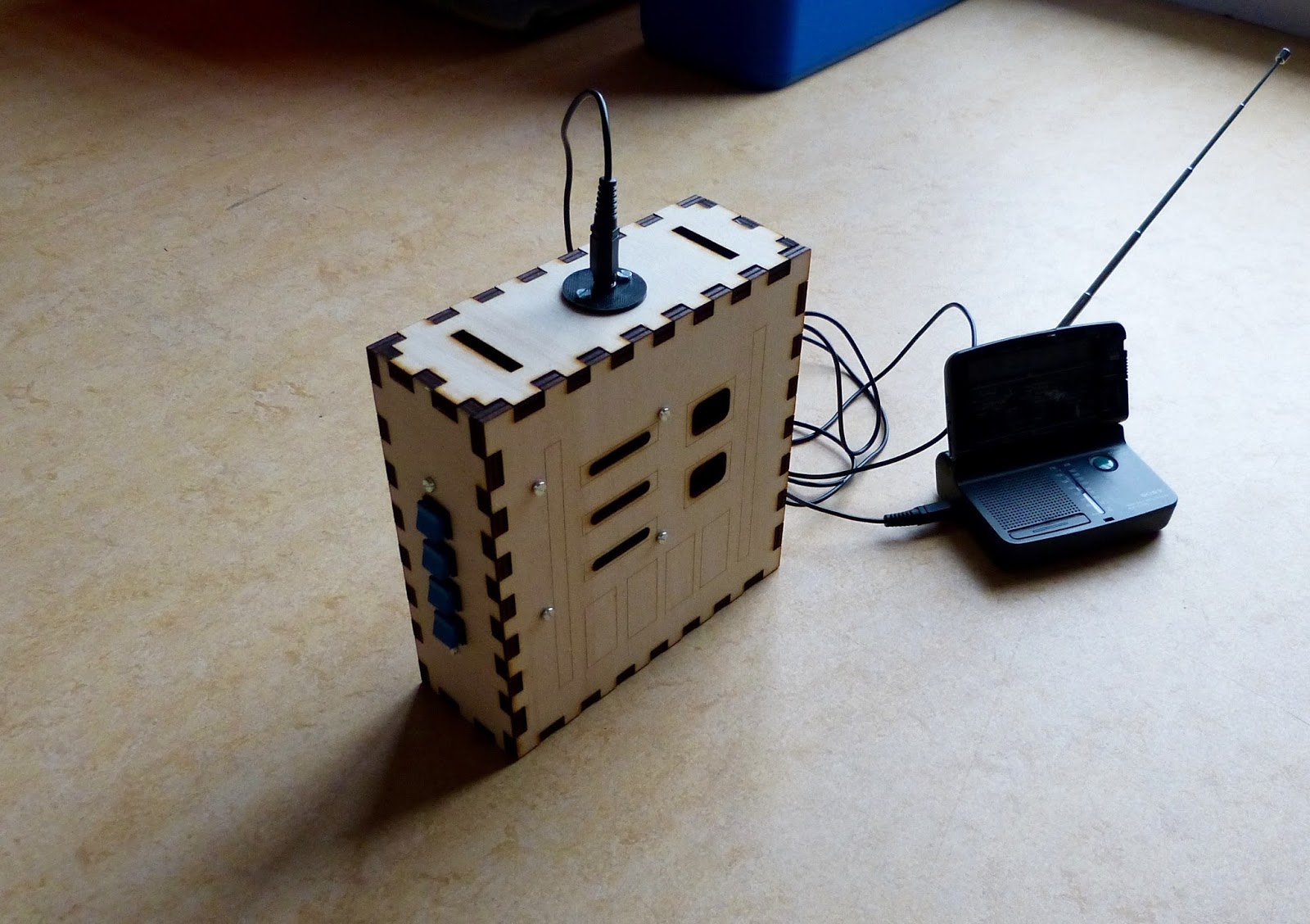
Chest box with FM radio connected to audio-in.

Finished chest box with laser cut parts glued to the front of the box.
Schematics of the Darth Vader chest box.

As a last step I wrote an instructable of the chest box providing anyone interested with the schematics, files for the laser cutter and 3D parts. In the mean time here are the links to the other blog posts on this chest box:
http://eribuijs.blogspot.nl/2015/12/darth-vader-voice-changer-20-ht8950a.html
http://eribuijs.blogspot.nl/2015/12/darth-vader-voice-changer-20-creating.html
http://eribuijs.blogspot.nl/2015/12/homemade-darth-vader-voice-changer-20.html
http://eribuijs.blogspot.nl/2016/01/designing-parts-for-darth-vader-chest.html
http://eribuijs.blogspot.nl/2016/01/the-darth-vader-chest-box-is-almost.html

Monday, January 11, 2016

The Darth Vader chest box is almost finished

Introduction

The last month I've been working on my Darth Vader chest box. I've designed and built my own circuit with the Holtek HT8950A voice modulator, I create a laser cut case and designed 3D printed parts for the chest box. Since I had to learn a lot of new techniques, e.g laser cutting and 3D printing, this is by no means an easy project for me. With the project in it's final stages now some design problems turn up that need fixing.

Soldering the board.

This week I soldered the components to the board. First I soldered the voice changer components and made sure this part of the circuit is working. Next I soldered the amplifier. I tested the total circuit and it worked the first time which is always a joyful moment. I find the Adafruit perma-protoboard very easy to work with since I'm able to copy the layout from the breadboard. Next I grouped all the buttons that operate the HT8950A on a board and soldered them to a piece perfboard. The buttons on the perfboard fit nicely into the laser cut side panel that I already made. Operating the chest box is easy with this (a major issue with my previous chest box).

Soldered perma-protoboard and breadboard side-by-side.
Close-up of the soldered board with the HT8950A voice changer chip on the right and the LM386 amplifier on the left.
Operating the voice changer with this panel should be easy.

Design issues

Last week I made 3D printed parts for the front of the chest box. Unfortunately I found that these parts didn't look good with the laser cut box. The plastic parts just didn't do justice to the laser cut plywood. I therefore decided to laser cut all the parts that sit on the from of the box with I think is aesthetically more pleasing.

Another problem arose with the female audio jack connector that I need to plug in the microphone. The thread of this 3.5mm connector just isn't long enough to be fitted onto the 6mm thick plywood. I designed a container to solve this. The audio connector fits into this container and the container is screwed to the case. Hopefully this container solves the problem.

Container for the audio jack connector created with Openscad. The container, screwed to the chest box, will keep the audio connector tightly to it's place.

Yet unsolved problems

  • I need to attach a nylon belt to the chest box. I'm thinking about popper snap fasteners attached to the belt to open or close the belt.
  • The HT8950A works fine with a proper audio signal as input but the microphone that I have, a small electret microphone, doesn't give any audible output (except for noise). I assume that the signal is to weak and therefore needs amplification.


Thursday, December 24, 2015

Homemade Darth Vader Voice Changer 2.0 (work in progress)

Introduction

The last couple of weeks I worked on a homemade voice modulator that is easy and cheap to built. First I'd like to mimic the Darth Vader Voice Changer, but with the press of a button it can be changed to robot or helium kind of voice effects. Last week I've steadily continued my work. The project has two main parts, the electronics and the case.

Electronic circuit

For the project I choose the HT8950A voice modulator from Holtek as the heart of the circuit. It is cheap, versatile and easy to work with. I previously had the voice modulator working. I only had to amplify the signal which seemed simple enough. Well, that turned out to be a bit more troublesome than expected. After connecting the LM386 to the circuit and powering it up an annoying hiss was introduced. After some experimenting I figured that the breadboard was to blame and decided to copy the circuit to another breadboard. Although on the new breadboard the hiss appeared somewhat reduced but it was still at an unacceptable level. Even when I removed the input signal from the LM386 the hiss continued. I connected the HT8950A with a audio-jack to an external amp. I wanted to make sure that the hiss was coming from the LM386. With the external amp the hiss was gone. The fact that I had hiss without an input signal indicated that the supplied voltage wasn't clean.  To clean it up I placed a small capacitor (10nF) from pin 6 (V+) to ground and voila the hiss was gone (see schematics below). It took me some time but I'm almost ready to finish this circuit and solder it to perfboard.

Two (almost identical circuits) with the Holtek HT8950A voice modulator and the LM386 amplifier. Both circuits gave a hiss which was unacceptable. Eventually a simple 10uF capacitor from pin 6 to ground did the trick for me. 
Schematics of the Darth Vader voice changer. I was able to eliminate all the hiss and noise from the LM386.

Printing the case.

I decided previously to make a T-slot plywood case for the Voice Changer but I'm not satisfied with the result. First I made a beginners mistake with the tab width. It was chosen poorly resulting in fragile edges of the case. Also I discovered that a T-slot case is not the best choice for this project. The case needs to be sturdy and the T-slot isn't. I'm afraid it will fall apart when in use. Therefore I'll made a regular finger joint that will be glued together. This new case was much better. Gone are the fragile edges and I'm confident that glued together it will be very sturdy.

Laser cut case made out of plywood. I first used a T-slot type of case but made a beginners mistake with the tab width and positioning. As a consequence the edges become very fragile. The front of the case has engravings for the positioning of large controls of the voice changer. These controls on the front will we dummies just to mimic the look of a Darth Vader voice changer. The actual controls will be on the side of the box.
Laser cut case with regular finger joint. This attempt is much better.

Monday, June 22, 2015

Making a Darth Vader voice changer, part 3

I finally finished the Darth Vader voice changer this weekend. I took a belt with two snap hooks from an old bag. Next I fitted the box with the voice changer with two black screw eyes that were large enough for the snap hooks. The enclosure is now comfortable around the neck of a child. In a local electronics shop I bought a case for a 9V battery that fitted nicely in the box. Finally I taped the mic into the Darth Vader mask and the fun could begin.

My two boys both volunteered and got dressed as Darth Vader.  We still have a dark cloak that goes well with the mask. Unfortunately we sold the lightsabers a couple of years ago. The Darth Vader voice is surprisingly convincing but only if you play around with the settings. Even funnier, you can make Darth Vader sound like a robot or as someone that has just inhaled helium (a very high pitched voice). I can imagine children having a lot of fun with the voice changer at a party or at Halloween.

Is there something left to be desired? Yes, the voice changer has four buttons for robot voice, vibrato, higher or lower pitch. As mentioned before I somehow couldn't get the external red push buttons functioning that were placed on the enclosure. So I used the pushbuttons on the MK171 board instead. To access the four pushbuttons on the MK171 board I need to open the enclosure. This is far from ideal and something that needs to be fixed in my next version of the voice changer.
Darth Vader complete with mask and cloak. Unfortunately the lightsaber is missing.

A Belt with two snap hooks, screw eyes and battery holder for a 9V battery complete the Darth Vader voice changer.

Enclosure, now with screw eyes.

Inside of the enclosure with battery holder.

Wednesday, June 10, 2015

Making a Darth Vader voice changer, part 2

About a week ago I wrote about a Darth Vader voice changer that I am making. I finally have finished a prototype but not without problem. I soldered all the external components to the Velleman MK171 kit. When I tested the circuit I discovered that three red pushbuttons (see images below) weren't functioning. I disconnected all four red pushbuttons and tested them on a breadboard with an LED. They all worked fine. I reconnected the buttons to the kit and again three of them didn't work. Running out of ideas and time I decided to use the regular mini pushbuttons instead that came with the kit. The voice changer works excellent and the sound is loud (due to the 2 inch speaker and the box) and resembles Darth Vaders however changing the voice requires opening the enclosure which is far from ideal.

There is still a little work left. I have to attach the mic to the inside of the Darth Vader mask and I need something to easily lock and unlock the back of the enclosure.

Image of the Darth Vader voice changer with the mic lying on top. The red pushbuttons are not attached to the pcb.
Back of the voice changer with the microphone wire.

Inside the enclosure of the voice changer. The pcb is mounted on the back of the enclosure.


Thursday, June 4, 2015

Making a Darth Vader voice changer, part 1

To be able to mimic Darth Vader during a party or any other occasion is a lot of fun. Unfortunately commercial solutions are costly. The Hasbro Star Wars Darth Vader Voice Changer costs $145 on Amazon. So why not make one myself. My voice changer will consist of the following parts: a cheap Velleman kit (MK171), a wooden enclosure for this kit and a simple plastic Darth Vader mask that we already have.

The MK171 kit consist of a PCB and all necessary electronic components. The most important component in the kit is the HT8950 chip. This 16 pin chip (from Holtek) is designed for voice modulation. The frequency of the input audio signal can be shifted up or down by the chip. Changing the output can be accomplished by four push buttons for: shifting frequency up, shifting frequency down, vibrato effect and robotic effect. For my purpose I'm interested in the frequency down function since this invokes a lower pitch to the listener, exactly what is needed for this Darth Vader type of voice. This way even a kids voice can be changed to Darth Vader's.

A small microphone is included in the kit to supply the input signal. I intend to integrate the microphone into the simple Darth Vader mask (possibly with velcro), close to the mouth. The sensitivity of the microphone is controlled by a trimmer. The output of the HT8950 is amplified by a LM386 OpAmp chip. With enough amplification and a proper speaker (not included in the kit) the sound effect can be overwhelming even when one speaks softly into the mic. Amplification is controlled by a yet another trimmer that is included in the kit.

The wooden enclosure is made of plywood. Four equal pieces of 15 x 7 x 1.2cm. The front and the back are made of 6mm thick plywood. Besides MK171 kit the enclosure needs to accommodate: control buttons for the  HT8950 chip, speaker, potentiometer to control the volume and an on/off switch.

Next step is to finish the enclosure and fit all external components. Then I need to test the MK171 kit with the external components before fitting it into the enclosure. Lastly complete the set with the mic integrated in the Darth Vader mask.

MK171 kit, wooden enclosure and Darth Vader mask. The three parts needed for the cheap Darth Vader voice changer. 
Work in progress. The enclosure of the voice changer with the external components. The four push buttons at the bottom left to control the HT8950 chip.
Spray painting the wooden enclosure in an improvised card board paint booth.

Thursday, May 14, 2015

Create a simple Audio Amplifier (LM386) part 2

Begin this week I created a simple Audio Amplifier with the LM386 (see previous entry). I noted that there was some noise coming from the speakers. I already had a 100uF capacitor on the breadboard to smoothen the power fluctuations. I searched the internet for solutions to further reduce the noise. I found three possible measures.
  1. Connect a 10uF to pin 7 of the LM386. In the schematics from HackaweekTV pin 7 (bypass) is not connected. On the website Learning About Electronics I found a tip to connect 10uF capacitor to this pin and ground it. Here is a link.
  2. On a another blog (Low Voltage. Mostly Harmless...) a 10nF capacitor is added to pin 6 and ground. Here is a link to this article.
  3. This is a feedback the LM386 output (pin 5) and pin 8. The feedback includes a 10k resistor and a 10nF capacitor in series. I found this tip here.
I included the three measures one after the other on my breadboard and then played some music. I found the the 1st and 3rd measure had a significant audible effect. The 2nd remedy, the 100nF capacitor added to pin 6, didn't have an audible effect. With the combined measures the noise was indeed reduced to a very acceptable level although it was not entirely gone.

For a video that demonstrates the Audio Amplifier see below.

Original 'noisy' circuit.

Improved circuit with significantly reduced noise. The 10uF capacitor between pin1 and 8 is removed. I didn't need the additional gain.

Sunday, May 10, 2015

Create a simple Audio Amplifier (LM386) part 1

While waiting for some components for Experiment 23 of Make: Electronics I decided to create a simple Audio Amplifier. I had a LM386 chip lying around which is more than adequate for this purpose. My first goal was to create an amplifier circuit with it on the breadboard and do some experimenting with it. Maybe I can use this set-up later as a simple amplifier for my sons ipods or android phones.

The LM386 is a low voltage chip making it ideal for a battery operated device. It has a OpAmp built in. See the image below for the pin layout. When pin 1 and pin 8 are not connected the gain is 20 but this can be increased to 200 if a 10uF capacitor is placed between these pins. Pin 4 and 6 provide supply voltage for the chip. Pin 3 is the input and a potentiometer connected to it will act as a volume control. Pin 5 is the output and can be connected to a speaker.

There is plenty of literature and schematics on the LM386 on the internet. For now I choose the one used by HackaweekTV on YouTube (https://www.youtube.com/watch?v=3KyBrAoHMX8). It uses a 10K potentiometer for volume control and a 10uF capacitor to increase gain.

Only a few components were needed so building it on a breadboard was straight forward. While testing it the amplification is excellent and the music sounds ok. Next time I will try to improve the circuit.

Pinout diagram of the LM386

Schematics of HackaweekTV used for this experiment 

Circuit on the breadboard with the audio jack and the speaker. On the left the 100uF smoothing capacitor.

Close-up of the LM386 and the connections to all the components.