Previously I added
555 timer in astable mode to generate pulses for the counter chips. In the next step a second 555 chip is added. This timer runs in bistable mode (see pg. 176 of
Make:Electronics). The purpose of this timer is to freeze the counting when the tactile switch is pressed (figure 4-40 of the book). The output (pin 3) of the timer is connected to pin 2 (disable pin) of the first 4026 decade counter. Adding this timer to the breadboard is straightforward. The only problem that I face is that the breadboard is becoming very crowded. The good news is that the circuit is almost finished. In the next step I will only have to add one more 555 chip.
 |
| Overview of the circuit which is becoming very crowded. |
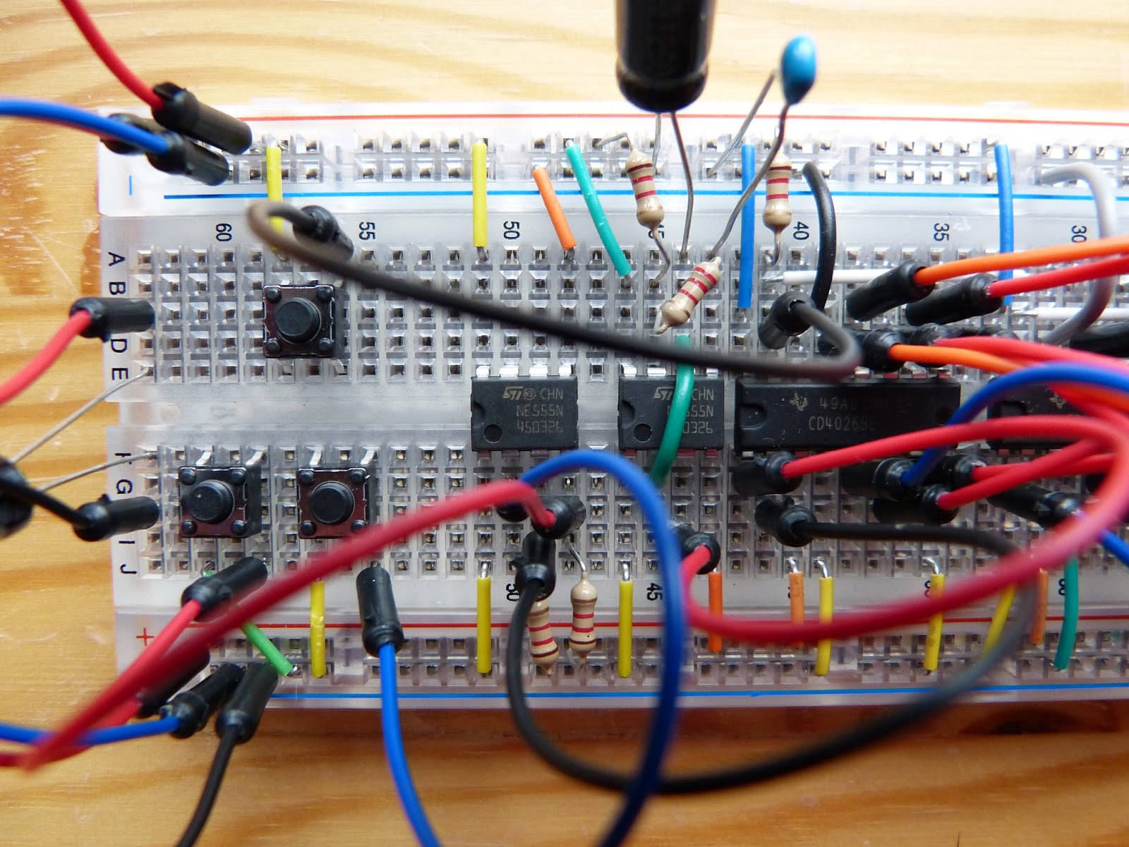 |
| Detail of the circuit with the two added 555 chips in the middle and the tactile switches left. |


No comments:
Post a Comment
Note: Only a member of this blog may post a comment.